")
")
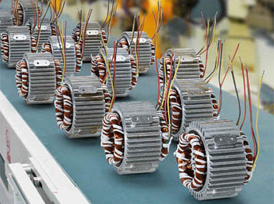

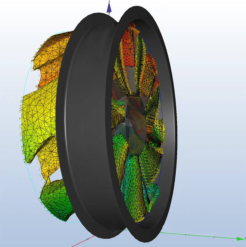
Turbulence effects with axial fans
The flow in an axial fan can be divided into two areas from the point of view of flow losses, the main or primary flow in the area of the center of the fan blade and the edge or secondary flows in the area of the hub and the fan ring (housing boundary).
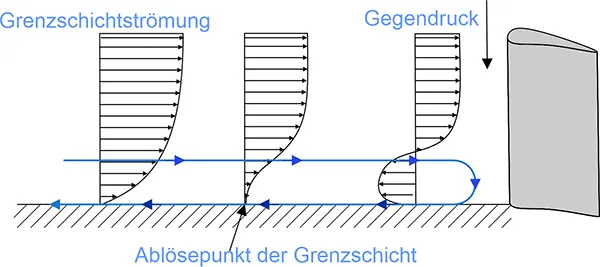
Boundary layer
When flowing along a wall with real friction at the surface, the velocity is close to zero due to the adhesive conditions of the air.
The flow velocity must therefore increase from the value of zero directly at the surface to a finite value near the wall. This is the boundary layer, which forms a characteristic velocity profile in the normal direction (perpendicular to the wall) to the surface until the outer flow is reached. Within this velocity profile, the velocity transition occurs.
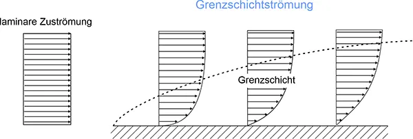
Outside the boundary layer the flow is laminar without large losses, inside the boundary layer the flow is lossy.
In the area of the leading edge of the axial blade, an accelerated boundary layer flow occurs. At the low subsonic velocities of our axial fans, this can rather be regarded as laminar with a low loss region. Only at the end of the blade suction side, turbulent boundary layer flows are to be expected due to the change from laminar to turbulent (transition point). The blades are designed in such a way that this transition point is located as far back as possible.
For sufficiently small Reynolds numbers, the fluid dynamic boundary layer is laminar and equidirectional to the main flow. The special conditions present in the boundary layer allow the pressure gradient perpendicular to the wall to be neglected: The pressure is approximately constant over the thickness of the boundary layer and is imposed by the main flow. Furthermore, the change in velocity in the direction parallel to the wall can be disregarded compared to that perpendicular to the wall.
Primary flow
The primary flow losses in the center blade area are influenced by the interaction with the airfoil geometry of the pressure and suction sides and the resulting airfoil boundary layers, which are responsible for the primary flow losses, the so-called airfoil losses.
These boundary layers on the pressure and suction sides increase in thickness over the chord length of the blade and combine at the trailing edge of the profile to form a wake dent.
 These losses are influenced by:Blade leading edge flow
-
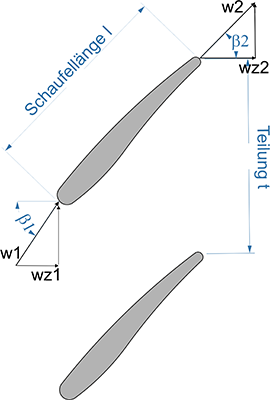
The pitch of the blade t
The inflow and outflow angles β1, β2
The momentum loss thickness Φ (measure of the reduction of the momentum flow in the boundary layer due to the influence of friction) to the chord length lthe axial velocities wz2/wz1
The resulting factors influencing the blade geometry on the primary flow are.
The pitch t of the blade, i.e., in simplified terms, the distance between the blades and, consequently, the number of blades on the hub. This should be appropriate for a given size and speed of the fan.
The flow velocity results from the nominal speed, which is roughly determined by the number of poles of the motor in the uncontrolled nominal state, and the size (height of the blades) by the desired volume flow to be achieved.
The inflow and outflow angles β1, β2 result from the blade pitch relative to the profile axis.
The axial velocities are influenced by the considered size of the axial blade and the incident flow velocity in axial direction (in height direction), which results iteratively from the volumetric flow taking into account the vertical section.
An improvement of the incident flow in axial direction in connection with the blade height results from the twisting of the blade in height direction.
Secondary flow
Secondary flow occurs outside the center of the blade as it gets closer to the sidewalls. The flow in the fan is limited on one side by the hub with the fixed blades and on the other side by the fan ring past which the blades rotate.
When pressure is built up on the boundary layer (see above) by the primary flow, the secondary flow is created. Due to the small flow velocities in the boundary layer, it can no longer keep the balance to the dynamic external pressure forces.
This leads to an increase in the boundary layer, which in turn reduces the effective free flow area. This leads to losses that account for a significant proportion of the total losses.
Secondary vortex
A distinction is made between the following vortex phenomena at the blade of an axial fan:
Ducted vortex
Horseshoe vortex
Trailing edge vortex
Corner vortices
These have a strong influence on the losses in the flow of the fan due to their turbulence.
Formation of the individual vortices:
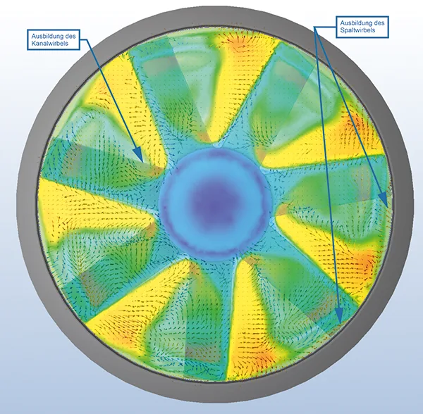
Duct vortex
Cross-channel flow results from the pressure gradient from the pressure side to the suction side of two blades. The resulting secondary flow in the boundary layer, results from the mutual influence of the deflection of the main flow and the sidewall boundary layers.
In the boundary layer, the air moves more slowly than the main flow with its strong momentum due to friction and the stronger curvature at the hub and blade wall. This results in a strong additional deflection of the flow due to the torsional forces, so that the boundary layers are twisted. This creates a vortex, the channel vortex, which builds up toward the end of the blade as the transverse pressure gradient becomes increasingly larger.
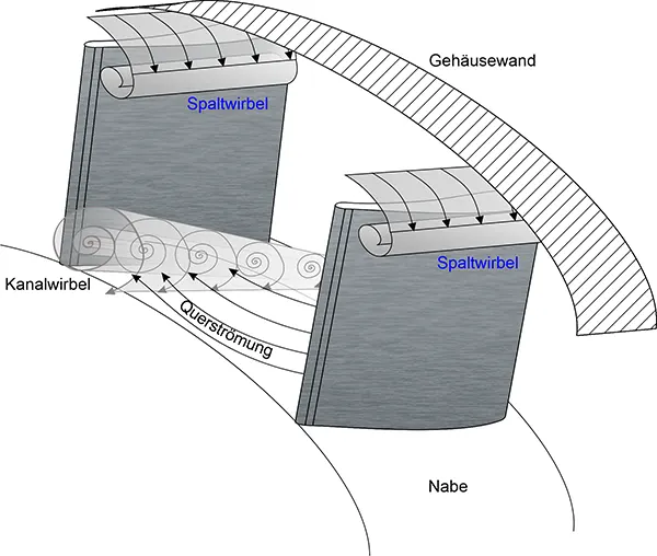
Gap vortex
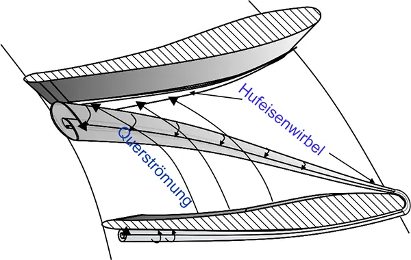
Horseshoe vortex
Horseshoe vortices develop at the leading edge of the blade. The impact creates a backflow in front of the axial blade and a counterpressure in the direction of the flow in the boundary layer. If this cannot withstand the counterpressure, detachment occurs.
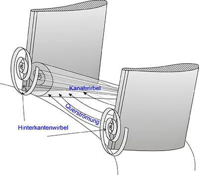
Trailing edge vortex
At the trailing edge of the blade, the channel vortices induce a pair of vortices. Outgoing air from the pressure side flows from the center of the channel to the side wall. This meets the air coming from the suction side, which rotates in the opposite direction. The shear layer that forms between the suction and pressure sides of the blade in the radial direction gives rise to the trailing edge vortices.
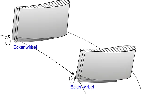
Corner vortex
When air is retarded by a boundary wall of the blade, a separation occurs within the boundary layer (see figure above). Due to the pressure gradient, a backflow is formed which rolls up to form a corner vortex. For a corner vortex to form, the air must strike the blade wall as vertically as possible, which is the case at the impact area of the cross-channel flow on the suction side.
on the suction side.
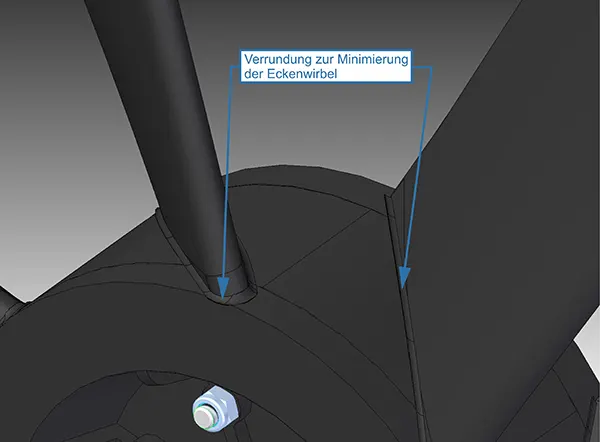
The intensity of the corner vortices can be weakened by rounding out the transitions at the blade root toward the hub. However, the fillet must not be too large, since excessively large radii will obstruct the airflow in the primary direction and new, intensified corner vortices will form.
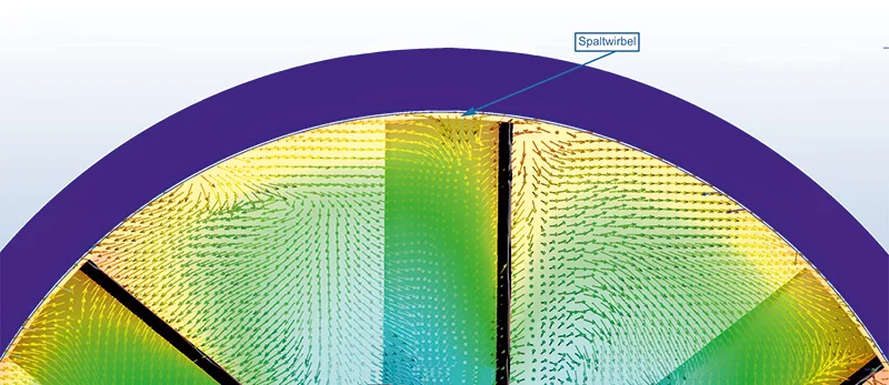
Gap vortex
The slot vortex is created between the housing wall and the axial blade as it rotates past. The air movement between the blade end and the housing causes the air to flow from the pressure side to the suction side. The air rolls up into a vortex, depending on the gap width, pressure difference and friction on the housing side (axial ring).
Since in axial fans the blade ends are narrow and the profile thickness is small in relation to the gap thickness, the pressure difference is the reason for the gap vortex.
There is a flow through the gap from the pressure side to the suction side and an interaction of boundary and gap flow, which can disturb the primary flow. In addition to the cross-channel flow already described, there is also the gap flow.
gap flow. The gap vortex has the opposite direction of rotation of the channel vortex. This can lead to a mutual influence of the cross-channel and gap flows rotating in opposite directions. The flow area for the main flow is reduced and losses occur. Therefore, in addition to reducing the duct vortex, it is also necessary to reduce the gap vortex by blade geometry and blade pitch.
To achieve a good efficiency of the fan, the following are required
- narrow airfoil geometries
- not too large angles of attack
- not too small pitch t are useful.
For a normal volume flow rate, the roll-up point of the vortex is located at the end of the blade geometry.
tends to be at the end of the blade geometry, increasing the inclination of its path to the main flow direction.
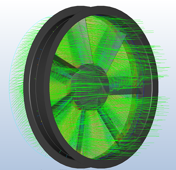
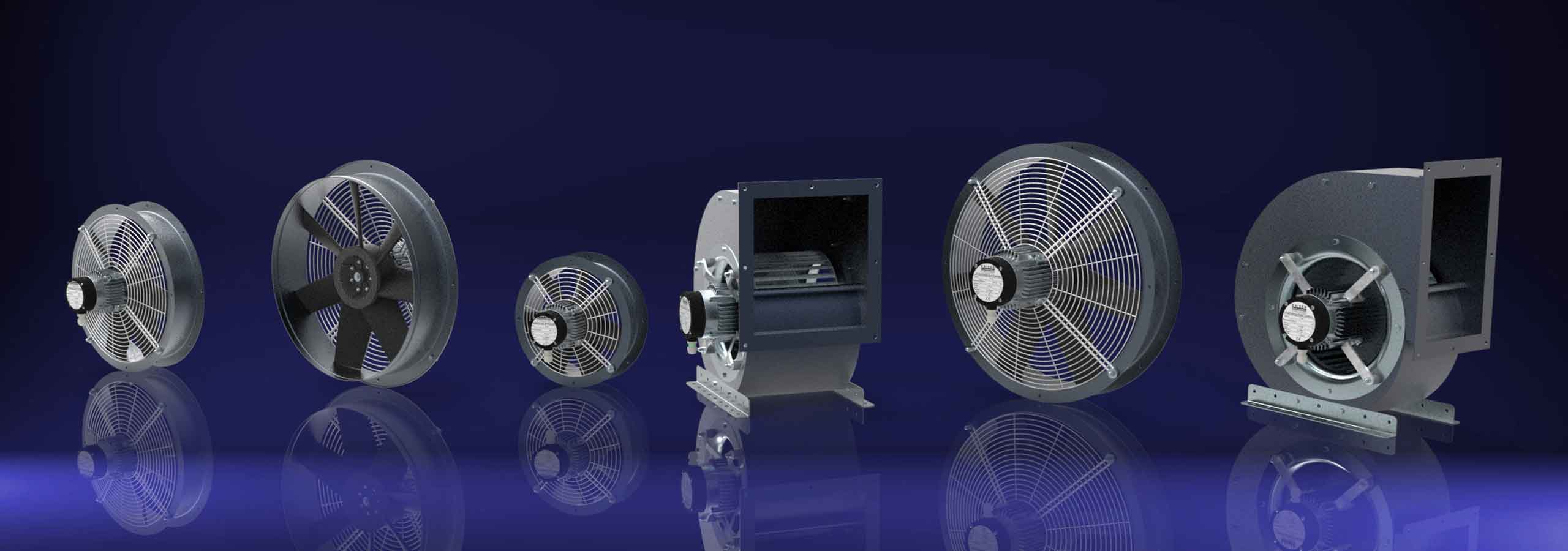
Reduction of losses in Kaiser axial fans
We were able to significantly improve the efficiency of axial fans through design measures.
Corner vortices due to rounding
Rounding at the blade root has reduced the formation of corner vortices.
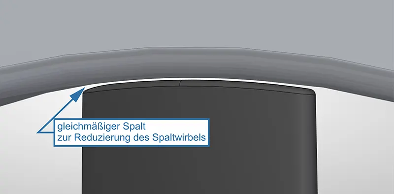
Gap vortices
2. the nip vortices could be successfully reduced by a uniform blade rounding, adapted to the diameter of the axial ring. Due to the uniform gap, turbulence effects in the gap are reduced.
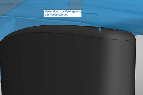
3. the rounding at the upper edge of the blade results in a reduced tendency of the flow to break off in the gap vortex area.
Primary flow
4. by changing the blade geometry with height, the angle of attack to the airflow could be optimized. As a result, an improvement of the primary flow has been achieved.
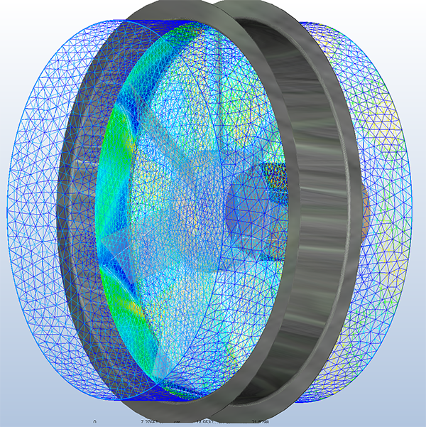
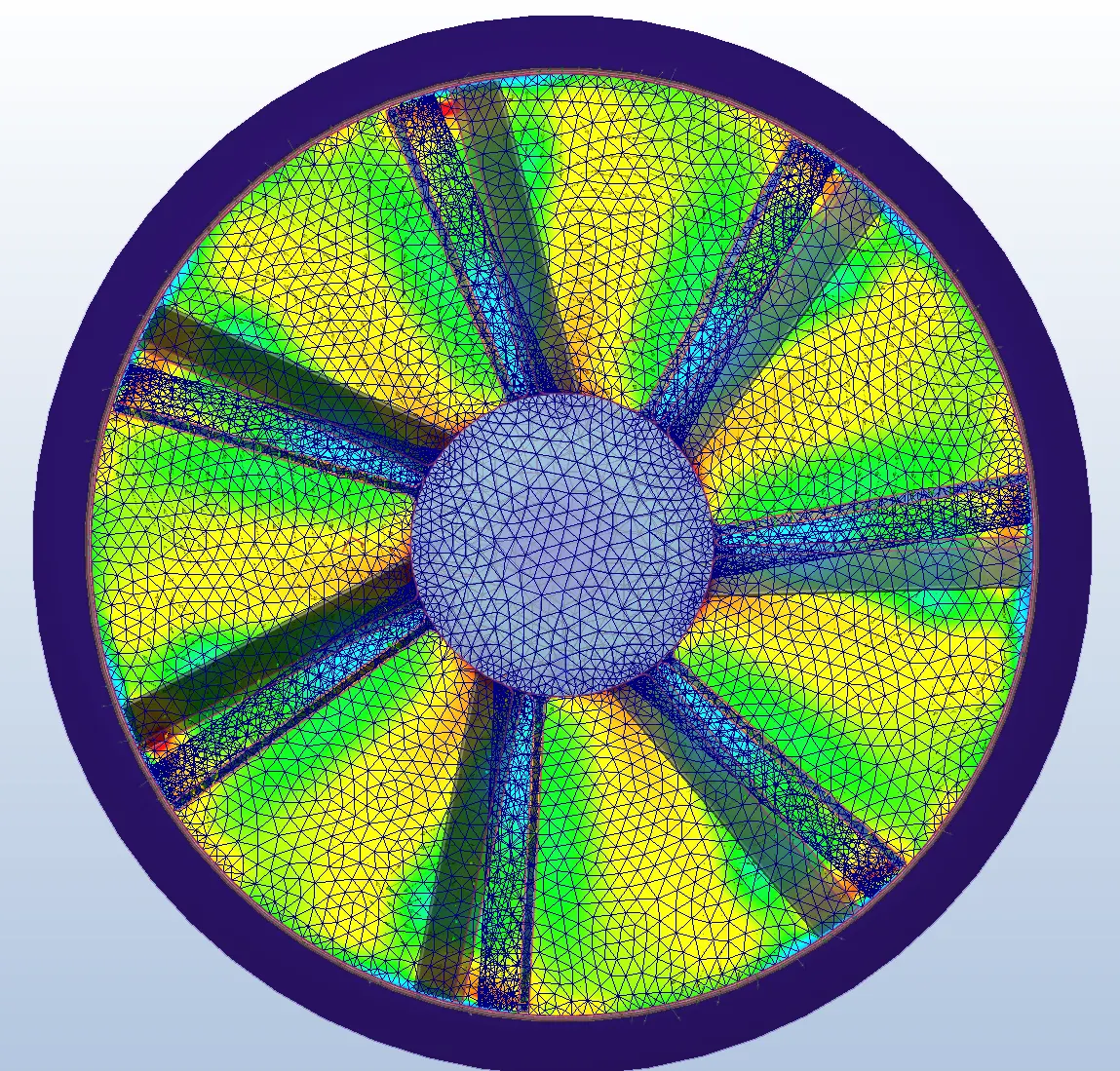
Turbulenz flow calculations KAISER axial fans